
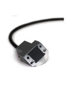
NM01X0AW001IH
Choose Quantity
Sonatest — X0AW-N60S-IHC Ultrasonic Wedge
60° Shear-Wave Wedge, 39° Cut Angle, 0 mm Delay Line, for Compatible X0 Transducers
SKU: X0AW-001-IH
Overview
The Sonatest X0AW-N60S-IHC is a 60-degree shear-wave ultrasonic wedge designed for angle-beam ultrasonic testing with compatible X0-series transducers.
Its acoustic geometry is specified for a nominal 60° refracted shear-wave angle in steel, using a 39° physical cut angle. This configuration allows ultrasonic energy to enter the test material at an angle, supporting weld examination, crack detection, structural inspection, and other applications where discontinuities may not be favorably oriented for straight-beam testing.
The wedge is specified with a 0 mm delay line, providing the intended X0-series acoustic configuration without an additional delay-line section. SKU X0AW-001-IH is suitable for professional ultrasonic inspection in fabrication, welding, maintenance, manufacturing, and industrial QA/QC environments.
What's Included
| Item | Details |
|---|---|
| Ultrasonic Wedge | Sonatest X0AW-N60S-IHC |
| Wedge Series | X0 |
| Wave Type | S — Shear Wave |
| Nominal Refracted Angle in Steel | 60° |
| Physical Cut Angle | 39° |
| Delay Line | 0 mm |
| Compatible Probe Type | Compatible X0-series transducers |
| Primary Application | Angle-beam ultrasonic inspection |
| Inspection Method | Ultrasonic Testing / UT |
| Manufacturer | Sonatest |
| SKU | X0AW-001-IH |
Note: Ultrasonic transducer, flaw detector, couplant, mounting hardware, calibration blocks, and other accessories are not included unless specified separately.
Box Dimensions & Shipping Weight (Estimated)
| Parameter | Imperial |
|---|---|
| Length | 6.0 in |
| Width | 4.0 in |
| Height | 3.0 in |
| Dimensions (L × W × H) | 6.0 × 4.0 × 3.0 in |
| Weight | 0.5 lb |
Actual shipping dimensions and weight may vary according to packaging and supplied mounting hardware.
Key Specifications
| Parameter | Details |
|---|---|
| Product Type | Ultrasonic angle-beam wedge |
| Model | X0AW-N60S-IHC |
| Wedge Series | X0 |
| Wave Type | Shear Wave / S |
| Nominal Angle in Steel | 60° |
| Cut Angle | 39° |
| Delay Line | 0 mm |
| Inspection Technique | Angle-beam ultrasonic testing |
| Compatible Transducer Family | X0-series compatible probes |
| Primary Use | Weld and flaw inspection |
| Coupling Method | Contact ultrasonic coupling |
| Inspection Method | Ultrasonic Testing / UT |
| Manufacturer | Sonatest |
| SKU | X0AW-001-IH |
Inspection Configuration
| Parameter | Details |
|---|---|
| Refracted Wave Mode | Shear wave |
| Nominal Refracted Angle in Steel | 60° |
| Physical Wedge Cut Angle | 39° |
| Delay-Line Length | 0 mm |
| Typical Technique | Angle-beam pulse-echo inspection |
| Probe Mounting | Compatible X0 transducer mounted to wedge |
| Couplant Requirement | Appropriate ultrasonic couplant |
| Calibration Requirement | Wedge delay, sensitivity, index, and angle verification |
| Typical Inspection Target | Welds, fusion zones, cracks, and internal reflectors |
The stated 60° angle is referenced to steel. Actual refracted angle can vary when the wedge is used on materials with different acoustic velocities.
Performance Features
60° Shear-Wave Configuration
Provides a nominal 60-degree refracted shear-wave sound path in steel for conventional angle-beam ultrasonic inspection.
39° Physical Cut Angle
The wedge geometry is machined to a 39-degree cut angle to generate the specified shear-wave behavior when used in the intended configuration.
0 mm Delay Line
Specified without an additional delay-line section, maintaining the intended X0 wedge geometry and acoustic path.
Designed for X0-Series Probes
Configured for use with compatible Sonatest X0 ultrasonic transducers.
Weld Inspection Capability
Supports examination of weld volumes, fusion zones, and adjacent base material where directional ultrasonic coverage is required.
Reusable Inspection Accessory
Can be used repeatedly when the contact surface, mounting surfaces, and acoustic interfaces remain in suitable condition.
Advantages of a 60° Shear-Wave Wedge
A 60-degree shear-wave configuration can provide useful sound paths for many industrial inspections.
Potential benefits include:
Directional examination of weld volumes
Evaluation of weld fusion zones
Detection of planar discontinuities
Inspection of defects not favorably oriented to straight-beam sound
Useful coverage of weld roots and sidewalls depending on geometry
Support for multi-angle inspection procedures
Practical use in structural steel inspection
Compatibility with conventional pulse-echo flaw detection
The correct wedge angle should always be selected according to component thickness, weld geometry, material, inspection code, and written procedure.
User-Friendly Design
Fixed 60° shear-wave configuration
Clearly defined 39° cut angle
0 mm delay-line specification
Designed for compatible X0 transducers
Suitable for field and shop inspection
Supports repeatable angle-beam setups
Compact accessory for portable ultrasonic equipment
Suitable for manual weld scanning
Supports conventional calibration procedures
Built for Industrial Inspection
Designed for professional ultrasonic testing
Suitable for fabrication and welding QA/QC
Practical for structural and maintenance inspections
Supports field and laboratory UT workflows
Useful for conventional flaw-detection procedures
Suitable for repeated manual scanning
Can be incorporated into documented inspection procedures
Intended for use with proper calibration and ultrasonic couplant
Compatibility
Compatible with:
Appropriate Sonatest X0-series transducers
Compatible ultrasonic flaw detectors
Conventional pulse-echo angle-beam systems
Suitable ultrasonic couplants
IIW and other applicable calibration blocks
Weld-inspection procedures
Carbon steel and other suitable materials
Field and laboratory ultrasonic-testing programs
Transducer fit, mounting hardware, frequency, material, required refracted angle, and instrument compatibility should be confirmed before ordering.
Ideal Applications
Weld inspection
Structural weld evaluation
Fabrication QA/QC
Pressure-vessel inspection
Pipeline weld inspection
Storage-tank weld inspection
Structural steel inspection
Machinery-component evaluation
Maintenance inspection
Crack detection
Lack-of-fusion evaluation
Weld-zone examination
Angle-beam flaw detection
Field ultrasonic testing
Industrial quality control
Typical Discontinuities Evaluated
When used with a properly calibrated ultrasonic system, the X0AW-N60S-IHC can support evaluation of discontinuities such as:
Cracks
Lack of fusion
Incomplete penetration
Slag inclusions
Planar reflectors
Weld-related discontinuities
Service-induced cracking
Other internal reflectors favorably oriented to the 60° sound beam
Detectability depends on flaw size, orientation, depth, material properties, probe frequency, sound path, and inspection technique.
Inspection Guidelines
Verify compatibility between the wedge and X0 transducer
Inspect the contact surface before use
Mount the transducer securely to the wedge
Apply coupling material between interfaces when required
Apply suitable ultrasonic couplant to the inspection surface
Calibrate wedge delay, range, and sensitivity
Verify the probe index or exit point when required
Confirm the refracted angle using an appropriate reference block
Position and scan the wedge according to the written procedure
Record relevant indications and sound-path information
Recheck calibration periodically during inspection
Angle and Material Considerations
The nominal 60° shear-wave angle is specified for steel.
When used on another material:
The refracted angle may change
Material sound velocity should be considered
Calibration should be performed on an appropriate reference block
Actual beam behavior should be verified before inspection
Sound path calculations should use the properties of the test material
Acceptance criteria should follow the governing inspection procedure
The physical 39° wedge cut angle should not be interpreted as the ultrasonic refracted angle inside the steel component.
Wedge Wear and Calibration
Wedge wear can affect the sound entry point, wedge delay, refracted angle, and inspection accuracy.
For reliable operation:
Inspect the contact surface regularly
Keep the wedge face clean
Avoid excessive abrasion
Verify wedge delay periodically
Confirm the exit point when required
Recheck the refracted angle as appropriate
Recalibrate after replacing the wedge
Replace heavily worn or damaged wedges
Avoid unauthorized grinding or reshaping
Protect the wedge from excessive heat unless specifically approved for such use
Care and Handling
Avoid dropping or striking the wedge
Keep coupling surfaces clean
Remove couplant after inspection
Inspect mounting surfaces for damage
Protect the contact face from scratches
Do not modify the 39° cut geometry
Store in a clean, dry location
Keep protected during transportation
Verify transducer fit before inspection
Replace the wedge if wear affects calibration or sound transmission
About Sonatest
Sonatest develops ultrasonic flaw detectors, phased-array systems, transducers, wedges, scanners, and related accessories for professional non-destructive testing. Its products support weld inspection, fabrication, manufacturing, maintenance, structural evaluation, asset integrity, and industrial quality-control applications.